
VLAN介紹和工業SIP電話配置。包括802.1Q、LLDP、CDP、DHCP VLAN、交換機中繼/訪問/混合設置和Cisco 2960 VLAN指南。
乙太網路是基於CSMA/CD(載波感測多重存取/碰撞偵測)的共用媒介網路技術。大量主機會造成嚴重資料碰撞、廣播風暴、效能下降與網路中斷。交換器可減少碰撞,但無法隔離廣播流量。
VLAN(虛擬區域網路)技術可將實體LAN分割為多個邏輯廣播網域,藉此解決上述問題。同一VLAN內的設備可如同在同一LAN內互相通訊;不同VLAN無法直接通訊,藉此限制廣播範圍。
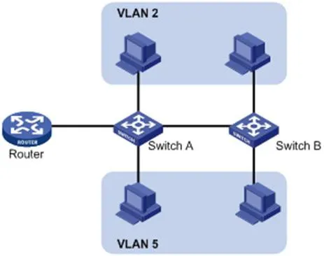
VLAN不受實體位置限制。設備可位於同一台交換器、跨越多台交換器,或穿越路由器,仍隸屬於同一VLAN。
VLAN的優點:
限制廣播網域、降低路由負載、減少延遲、節省頻寬並提升整體效能。
強化資安:VLAN間進行第二層隔離,跨VLAN通訊需依賴第三層路由。
彈性虛擬工作群組:無需變更實體佈線,即可對使用者進行邏輯分組。
為辨識VLAN訊框,會在資料鏈結層(第二層)的乙太網表頭加入VLAN標籤。
IEEE於1999年制定802.1Q協定做為VLAN標籤的標準規範,定義了在乙太網封包中加入VLAN資訊的標準方式。
802.1Q會在來源MAC位址與EtherType欄位之間插入一個4位元組標籤:
2位元組:TPID(標籤協定識別元)
2位元組:TCI(標籤控制資訊)
TCI包含PCP(優先權編碼點)、CFI(標準格式指示器)與VID(VLAN識別元)。

圖 1-2 傳統乙太網訊框格式
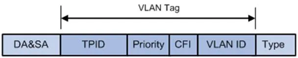
圖 1-3 VLAN標籤欄位
VLAN標籤欄位說明:
TPID:16位元,辨識802.1Q標籤;預設值 0x8100。
Priority(優先權):3位元,對應802.1p服務等級(CoS)。
CFI:1位元,MAC位址格式;0 = 標準格式,預設值 0。
VLAN ID:12位元,用來識別VLAN;有效範圍1–4094(0 與 4095 為保留編號)。
備註:雙標籤(QinQ)訊框僅由交換器處理外層標籤,內層標籤會視為負載資料。
LLDP(鏈結層探索協定)可讓網路設備在區域網路內公告並接收鄰居設備資訊。資訊會儲存於MIB,可透過SNMP(RFC 2922)查詢。
LLDP採用TLV(型別/長度/數值)結構承載設備資訊,多個TLV組成一筆LLDPDU(LLDP資料單元)。
| 型別 | 長度 | 數值 |
| 7 位元 | 9 位元 | 0-511 位元組 |
圖 1-4 TLV結構
LLDP-MED(媒體端點探索)為VoIP設備專用擴充規格,提供以下功能:
設備能力探索
語音VLAN組態
PoE電源管理
資產盤點管理
緊急來電位置辨識
備註:LLDP 與 LLDP-MED 無法在同一連接埠同時執行。
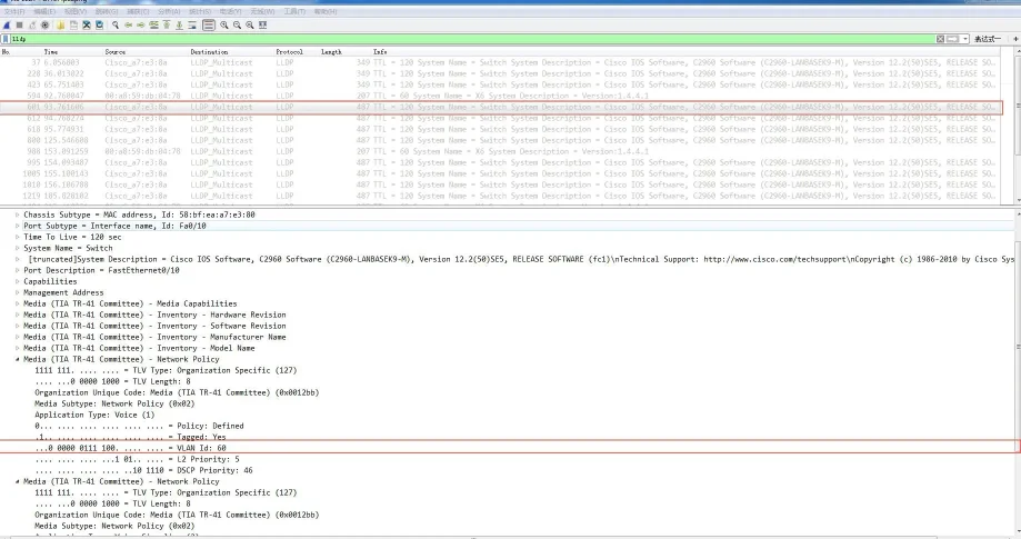
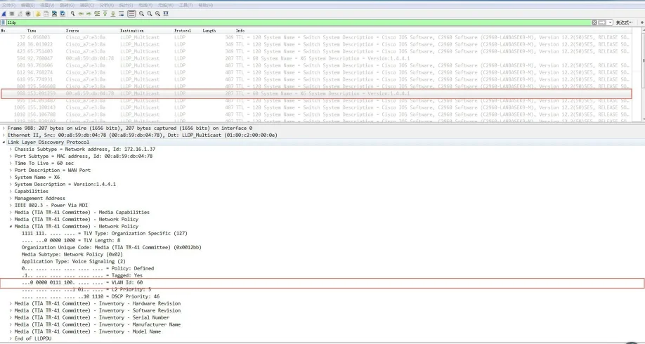
IP話機的LLDP功能:
啟用LLDP後,話機會週期性發送自身資訊並監聽交換器封包。若應用類型 = 語音,話機會自動從交換器學習語音VLAN ID、更新組態並重新開機套用VLAN。
LLDP組態步驟(網頁介面):
使用admin/admin登入網頁管理介面。
前往 網路 → 進階設定。
啟用 LLDP。
設定傳送間隔(1–3600秒)。
點擊套用並重新啟動話機。
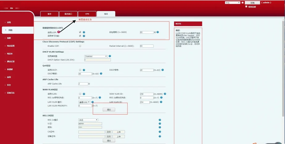
圖 1-5 LLDP組態介面
啟用LLDP後,話機具備以下行為:
週期性發送群播LLDP封包。
於WAN/LAN連接埠接收LLDP封包。
支援MAC/PHY組態設定。
透過網路政策TLV取得VLAN(覆蓋手動設定)。
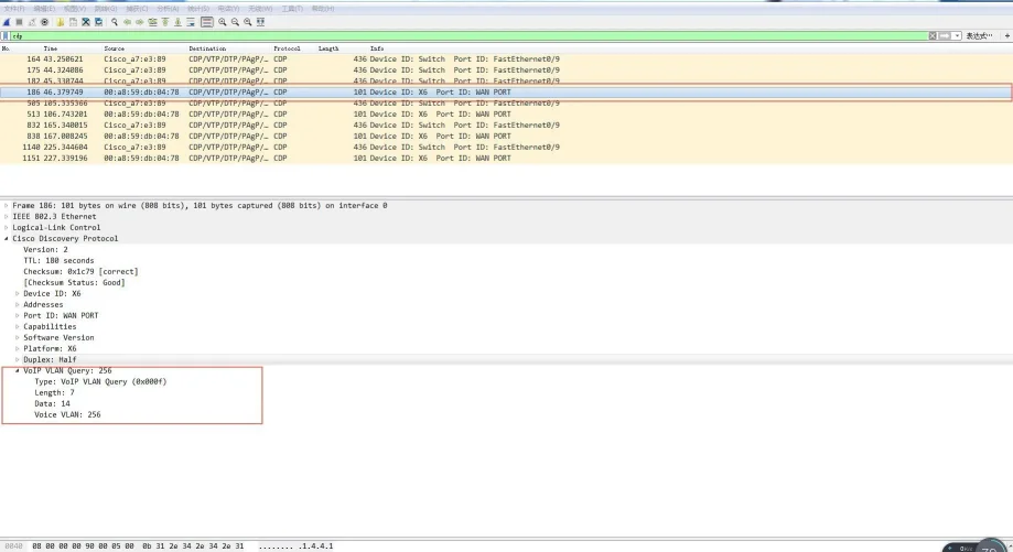
CDP(Cisco探索協定)是Cisco專屬的第二層設備探索協定。
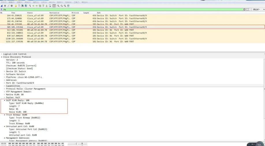
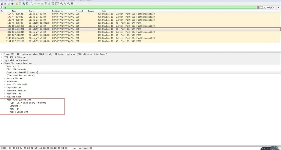
IP話機的CDP功能:
話機會公告自身資訊並監聽交換器的CDP封包,自動學習語音VLAN ID、更新組態後重新開機。
CDP組態步驟(網頁介面):
使用admin/admin登入。
前往 網路 → 進階設定。
啟用 CDP。
設定訊息傳送間隔(1–3600秒)。
點擊套用。
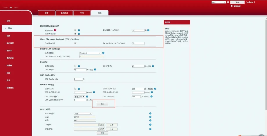
圖 1-6 CDP組態介面
話機支援透過DHCP自動探索VLAN。預設使用Option 132取得VLAN ID,最多支援5組自訂DHCP選項。
DHCP VLAN組態步驟(網頁介面):
使用admin/admin登入。
前往 網路 → 進階設定。
啟用 DHCP VLAN。
輸入DHCP選項編號(例如 132)。
點擊套用。
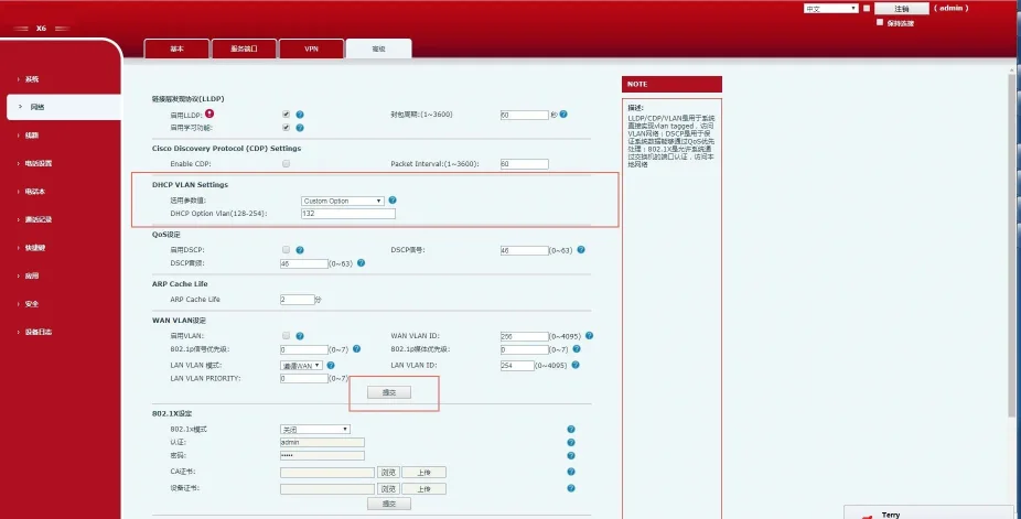
圖 1-7 DHCP VLAN組態介面
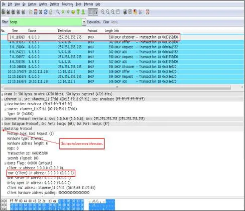
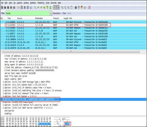
運作流程:
話機廣播送出DHCP Discover封包。
伺服器回覆包含Option 132(VLAN ID)的封包。
話機釋放現有IP、將所有流量標上學習到的VLAN ID,並重新發起DHCP請求。
VLAN預設為停用。可分別針對WAN(網際網路)連接埠與LAN(電腦)連接埠獨立設定VLAN ID 與 802.1p 優先權(0–7,7為最高優先權)。
WAN VLAN設定(網頁介面):
使用admin/admin登入。
前往網路 → 進階設定。
啟用 VLAN。
設定 WAN VLAN ID(1–4094)。
設定優先權(0–7)。
點擊套用。
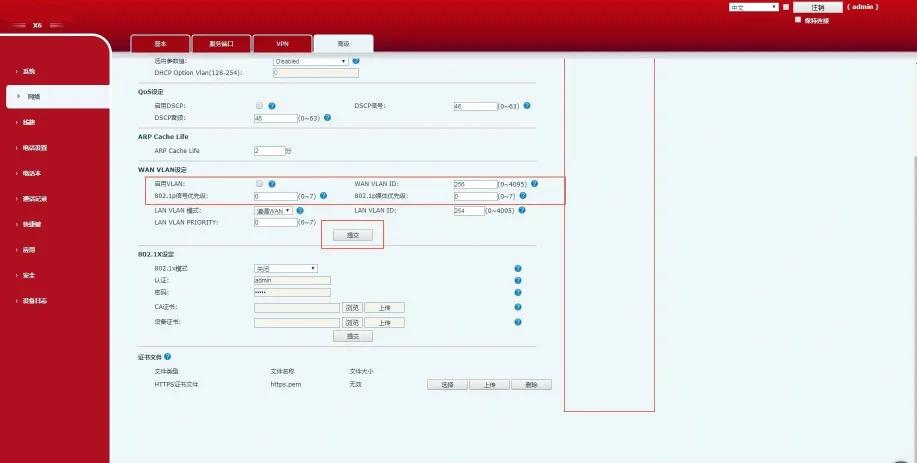
圖 1-8 WAN VLAN設定
LAN VLAN設定(網頁介面):
使用admin/admin登入。
前往 網路 → 進階設定。
設定 LAN VLAN 模式與 ID。
設定優先權。
點擊套用。
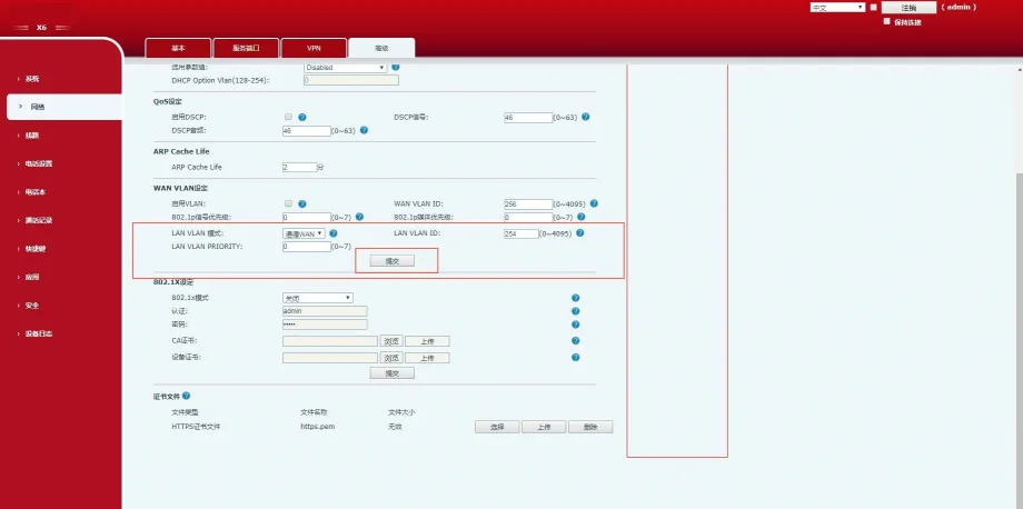
圖 1-9 LAN VLAN設定
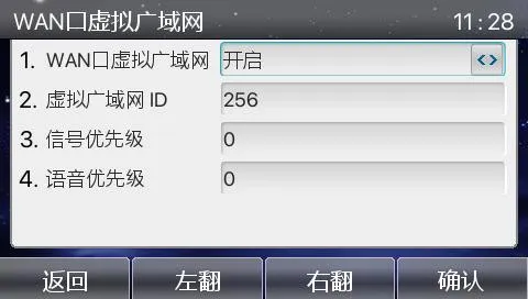
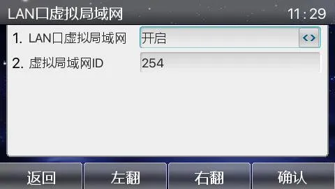
話機LCD畫面VLAN設定:
選單 → 進階設定(密碼:123) → 網路 → QoS&Vlan → WAN VLAN / LAN VLAN
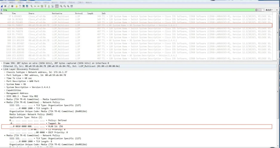
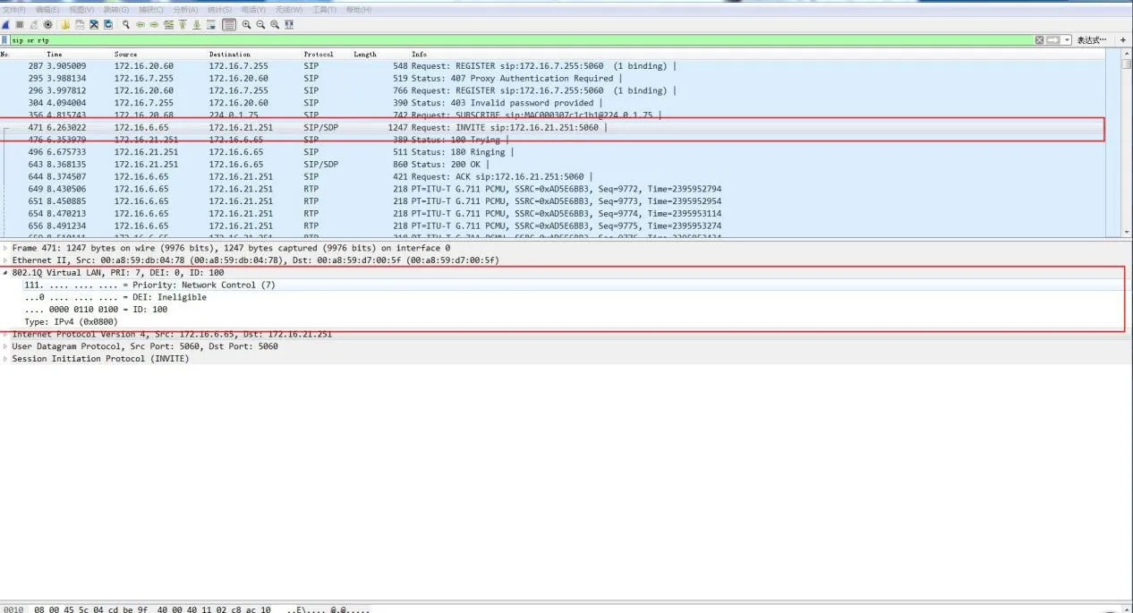
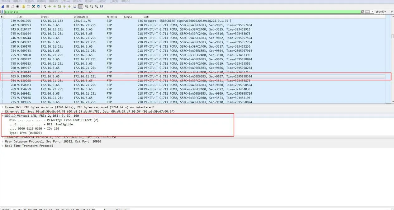
組態驗證:
擷取網路封包,確認SIP與RTP訊框內的802.1Q標籤、VLAN ID及802.1p優先權是否正確。
乙太網交換器連接埠支援三種模式:
Access(存取模式):隸屬單一VLAN;用於終端裝置(電腦)連接。
Trunk(中繼模式):承載多個VLAN;用於交換器之間互連。
Hybrid(混合模式):承載多個VLAN;支援自訂無標籤輸出。
核心規則:
Tagged(含標籤):訊框送出時保留802.1Q VLAN標籤。
Untagged(無標籤):交換器於送出前移除VLAN標籤。
PVID(連接埠預設VLAN):指派給無標籤入埠訊框的預設VLAN。
| 連接埠類型 | 入埠處理 | 出埠處理 | |
| 接收無標籤訊框 | 接收含標籤訊框 | ||
| Access | 加入PVID標籤 | 非所屬VLAN則丟棄 | 移除標籤並轉送 |
| Trunk | 允許則加入PVID標籤 | 允許的VLAN才接收 | 僅VLAN等於PVID時移除標籤 |
| Hybrid | 允許則加入PVID標籤 | 允許的VLAN才接收 | 依連接埠組態決定保留或移除標籤 |
| 參數 | 預設值 | 範圍 |
| VLAN ID | 1 | 1–4094 |
| VLAN 名稱 | VLANxxxx | — |
| MTU | 1500 | 1500–18190 |
| 狀態 | 啟用 | 啟用/暫停 |
| 步驟 | 指令 | 用途 |
| 1 | configure terminal | 進入全域組態模式 |
| 2 | vlan | 建立或編輯VLAN |
| 3 | name | 設定VLAN名稱 |
| 4 | end | 退出至特權模式 |
| 5 | show vlan | 檢查組態 |
| 6 | copy running-config startup-config | 儲存組態 |
| 步驟 | 指令 | 用途 |
| 1 | configure terminal | 進入全域組態模式 |
| 2 | no vlan | 刪除指定VLAN |
| 3 | end | 退出組態模式 |
| 4 | show vlan brief | 驗證刪除結果 |
| 步驟 | 指令 | 用途 |
| 1 | configure terminal | 進入全域組態 |
| 2 | interface | 選擇欲設定的連接埠 |
| 3 | switchport mode access | 設為存取模式連接埠 |
| 4 | switchport access vlan | 指派隸屬VLAN |
| 5 | end | 退出組態模式 |
| 步驟 | 指令 | 用途 |
| 1 | configure terminal | 進入全域組態 |
| 2 | interface | 選擇欲設定的連接埠 |
| 3 | switchport mode trunk | 設為中繼模式連接埠 |
| 4 | switchport trunk native vlan | 設定原生VLAN |
| 5 | end | 退出組態模式 |
switchport trunk allowed vlan { add | all | except | remove }
switchport trunk native vlan
Cisco 2960 系列交換器