
本指南說明如何使用音頻輸出/線路輸出和具有完整接線和Web UI設置的繼電器觸發模式來控制工業SIP對講機上的外部放大器音頻輸出。
當工業設備連接到外部擴大機時,您可以根據應用場景控制是否將音訊輸出到擴大機。 在正常通話期間,擴大機應關閉,僅使用內建揚聲器。在廣播或緊急廣播期間,必須啟動擴大機。 本文說明適用於不同設備型號的兩種控制方法。
BHP‑SOS10, BHP‑SOS10V, BHP‑SOS10D, BHP‑SOS11V, BHP‑SOS11V2, BHP‑SOS16, BHP‑SOS16V, BK‑ROIP‑PA2, BK‑ROIP‑PA2S, BK‑ROIP‑PA3, BHP‑SOS12.
① 一台支援的設備(以 BHP‑SOS16V 為例)、PoE 交換器(或 DC 電源)、一台擴大機、一個喇叭。將擴大機連接到設備,並將喇叭連接到擴大機。將設備連接到交換器。
② 一台調試電腦,連接到同一台交換器,以確保網路連通性。
將 BHP‑SOS16V 和電腦連接到同一台交換器。連接圖如圖 1 所示。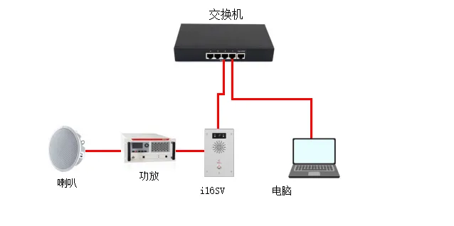
圖 1 設備與電腦連接圖
可以透過啟用音訊輸出介面或使用繼電器切換擴大機電源來控制擴大機輸出。兩種方法說明如下。
此方法適用於:BHP‑SOS10 系列、BHP‑SOS11 系列、BHP‑SOS16 系列、BK‑ROIP‑PA2、PA2S、PA3。
注意:BK‑ROIP‑PA2/PA2S 使用 Headset 介面;PA3 使用 Line Out。i10/i11 系列需要自訂 2 針 MX1.25 接線。
透過網頁介面設定:
(1) 登入網頁介面(預設使用者名稱/密碼:admin)。
(2) 前往 對講機設定 → 媒體設定 → 媒體設定。
將 啟用外部喇叭 設定為 免持與線路輸出。
將 線路輸出觸發狀態 設定為 對講被叫方。
參數說明:
免持與線路輸出:同時啟用免持音訊和線路輸出音訊。
線路輸出觸發狀態:
響鈴:響鈴時觸發
主叫方(通話中):撥打電話時觸發
SIP 被叫方(通話中):接收 SIP 來電時觸發
多播被叫方:接收多播時觸發
對講被叫方:接收對講來電時觸發
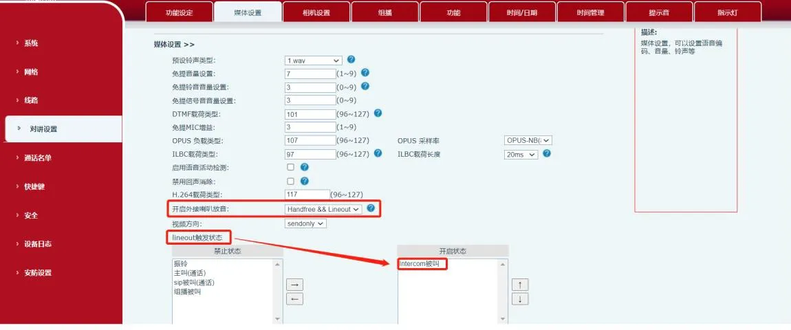
圖 2 音訊輸出控制圖
此方法適用於所有列出的型號,包括 BHP‑SOS12。 (1) 輸出埠規格
| 型號 | BHP‑SOS12 | BHP‑SOS16/16V | BHP‑SOS10/11V/PA2 | BK‑ROIP‑PA2S |
| 輸出埠數量 | 2 | 2 | 1 | 1 |
| 額定值 | DC 30V/1A AC 30V/1A | DC 30V/2A AC 125V/0.5A | DC 30V/1A AC 125V/0.5A | DC 30V/1A AC 125V/0.5A |
(2) 擴大機接線(乾接點範例)
① 對於 BHP‑SOS16V 外部電源模式:連接 JP1 的引腳 2‑3,引腳 1 和 4 懸空,如圖 3 所示。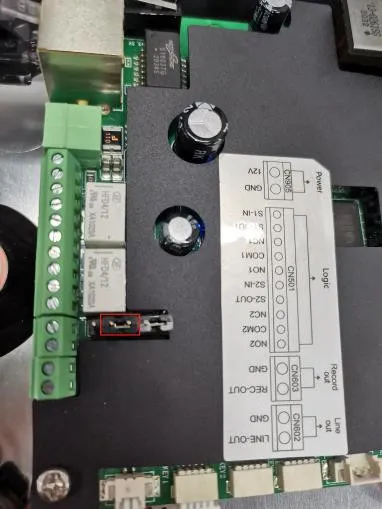
圖 3 跳線連接圖
② 接線:
- 電源正極 → 擴大機正極
- 電源負極 → 設備 COM
- 擴大機負極 → 設備 NC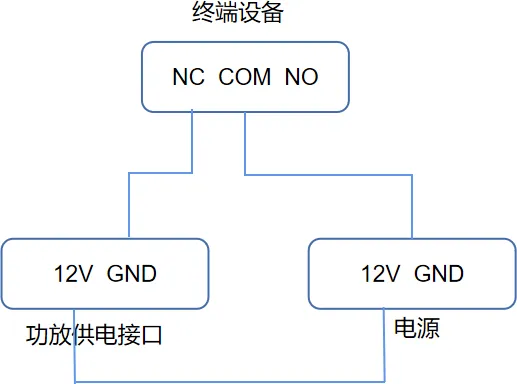
圖 4 擴大機接線圖
③ 音訊接線:
- 擴大機左聲道音訊 → 設備 Audio Out +
- 擴大機 GND → 設備 GND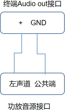
圖 5 音訊輸入接線
(3) 輸出埠設定
① 前往 安全性設定 → 輸出埠設定。
② 勾選 輸出埠 1(或 2)。
③ 勾選 依通話狀態觸發 並啟用 對講被叫方。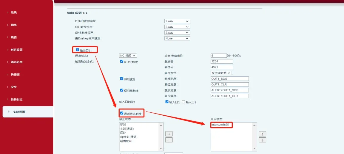
圖 6 輸出埠設定
當設備收到 對講被叫方 事件時,COM 與 NC 閉合,開啟擴大機。