LED指示燈是一種小型視覺訊號裝置,透過發光二極體顯示設備、系統或電路的運作狀態。在實際產品中,常用於顯示電源狀態、通訊活動、警報狀況、充電狀態、網路連線、故障警告或製程狀態。雖然元件結構簡單,但在實務系統中扮演重要角色,可將電氣或邏輯狀態轉化為人類一目了然的資訊。
換言之,LED指示燈不只是單純會亮的燈具,更是人機介面的一部分。綠燈通常代表正常運作、琥珀燈為警示、紅燈則表示異常或需緊急處理。同一台設備上,恆亮與閃爍也會代表兩種不同狀態。這也是為什麼從IP電話、工業電話、網路交換器、控制櫃、閘道器、電力錶、醫療設備到公共安全裝置,隨處可見LED指示燈。

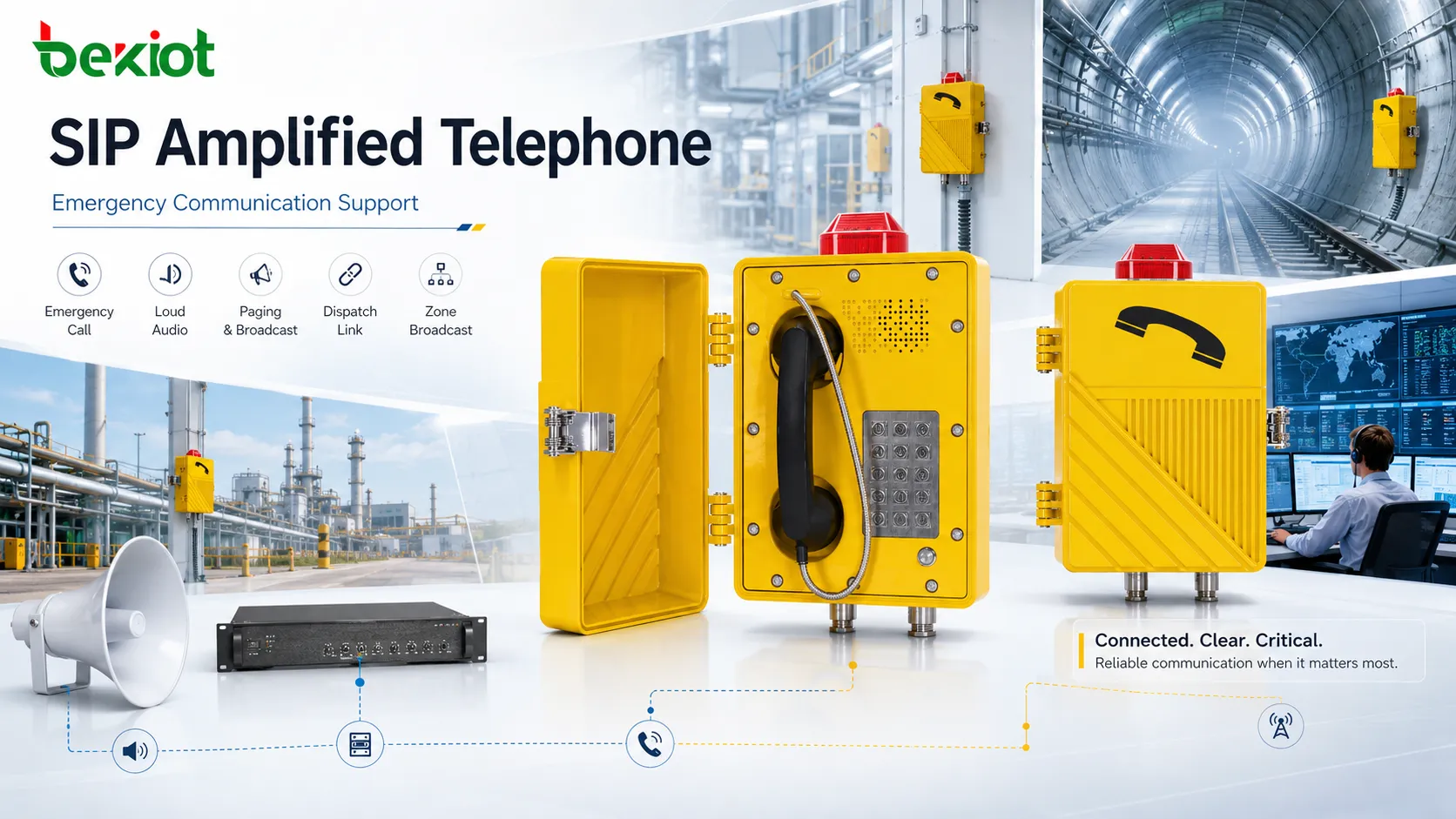
LED指示燈常配置於設備前面板,即時提供電源、通訊與警報狀態的視覺回饋。
何謂LED指示燈
LED指示燈是以發光二極體為核心的視覺狀態元件。當電流通過二極體時便會發光;在設備設計中,此光源做為狀態指示而非一般照明用途。指示燈可直接焊接於電路板、整合於面板、安裝在透明鏡片後方,或內建於按鍵、按鈕、警示燈模組之中。
燈號的實際定義依產品設計而定。網路設備的LED可顯示連線狀態、資料活動、PoE模式、風扇運作或系統警報;電力錶用來呈現心跳訊號、通訊狀態或異常警示;充電器則標示充電中、電池滿載或電池故障;工業終端機可顯示緊急呼叫啟用、網路註冊完成或系統錯誤。單一基礎元件,可對應多種互動模式。
LED指示燈體積小、反應快、易辨識,已成為將隱藏式設備邏輯轉為可視化運作資訊的標準方案。多數技術人員在使用軟體工具或三用電表前,都會優先查看LED燈號。
LED指示燈運作原理
元件層面來說,電流通過半導體接面時,發光二極體便會發光。電子裝置中,LED大多由控制電路、微控制器輸出、電源軌、邏輯介面或專用驅動晶片驅動。系統會決定指示燈關閉、恆亮、閃爍、調光或變色的時機。
簡易電路中,LED指示燈可直接判斷電源是否供電;進階設備則透過韌體控制燈號樣式,反映內部狀態。例如恆亮綠燈代表正常、綠燈閃爍代表資料傳輸;琥珀恆亮為輕微警示、紅燈代表嚴重故障。部分產品也會使用藍燈、白燈、雙色LED,做為定位、配對或維護模式指示。
這代表LED指示燈是大型資訊傳輸路徑的可視化終端:
設備偵測電源開啟、網路連線、警報、輸出入活動等狀態。
控制邏輯將偵測條件對應至LED燈況。
LED驅動器依照定義模式供電點亮二極體。
使用者解讀視覺訊號並做出對應處置。
這套簡單流程,說明指示燈設計的重要性。若配色、閃爍邏輯、鏡片可視性設計不佳,容易導致人員誤判設備狀況。完善的燈號設計能減少人為猜測,提升操作與維護的反應速度。
LED指示燈佈建優勢
LED指示燈廣泛應用並非潮流,而是可一次性解決多項工程實務問題。具備高可視性、高效率、反應快速、體積精簡,易整合於各式大小設備。
1. 即時視覺回饋
最直觀的優點便是狀態即時可見。使用者無需登入系統、開啟軟體或外接量測儀器,就能快速判斷設備供電、連線、充電、異常與否,大幅縮短反應時間,提升辦公室、工業廠區、交通樞紐、控制室的使用便利性。
2. 低功耗
相較傳統白熾燈,LED擁有極佳能源效率。在設備設計中,每瓦特功耗都會影響散熱、電源預算、電池續航與PoE配置;狀態指示燈需清晰傳達資訊,同時避免多餘耗電。
3. 使用壽命長
耐用度是LED受青睞的關鍵因素。使用壽命越長,更換次數、維護中斷與後續維運成本越低。安裝於天花板、道路箱體、公用設備、離岸廠房、製程區域的設備,減少燈號更換次數,能帶來實質營運優勢。
4. 體積小巧、整合彈性高
LED可內建於按鍵、外框、前面板、警示塔燈、緊急按鈕與微型嵌入式裝置。設計人員可依空間限制,選用單色、雙色、RGB燈號,容納多種狀態顯示需求。
5. 瞬間反應與燈效控制
相較傳統警示燈,LED切換快速且精準,可實現恆亮、脈衝、心跳閃爍、交替變色、優先警報等多種燈效。通訊設備中,閃爍燈號比靜態文字更能有效呈現資料活動。
6. 低發熱、提升穩定性
LED高效率與精簡體積,相較舊式指示技術更少多餘廢熱。密閉式設備中,可優化整體散熱設計,尤其適用於單一面板配置大量狀態燈號的情境。
優質的LED指示燈,不只是單純發光。能縮短故障診斷時間、強化操作人員信心,並讓現場設備運作狀況更容易理解。
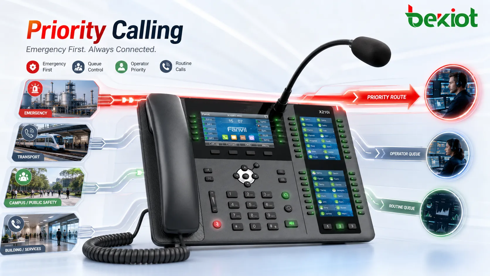
通訊與網路設備中,LED常透過顏色與閃爍規律,區分正常運作、資料活動、警示與異常狀態。

實際設備常見LED燈號功能
LED外觀雖然簡潔,但不同產品顯示資訊差異極大,常見用途如下:
電源指示:顯示設備是否通電、正常運作。
狀態指示:顯示待機、執行、網路註冊、就緒、忙碌模式。
警報指示:標示警示、硬體異常、超載、緊急狀況。
通訊指示:顯示網路連線、序列傳輸、輸出入狀態、資料傳輸。
充電指示:顯示充電進度、電池滿載、充電異常。
維護指示:提示需保養、風扇異常、儲存故障、模組異常。
定位指示:協助技術人員在機架、機櫃中快速辨識目標設備。
專業設備即便無產業統一規範,同系列產品通常會統一燈號定義。因此設備手冊至關重要,不同廠商的綠燈含義、閃爍模式皆可能不同。
LED指示燈維護須知
LED本體結構簡單且耐用,但周邊系統並非如此。燈號不亮、卡死、亮度不足、色偏,可能源自電源、配線、韌體、驅動電路、感測器、通訊模組或燈本體異常。完善維護需同時檢視指示燈與後端系統。
優先查閱產品手冊
判定LED故障前,務必先確認燈色與閃爍定義。多數設備開機、設定、輪詢期間,琥珀閃爍屬正常現象;誤讀狀況是最常見的維護失誤。
檢視鏡片、視窗與安裝區域
灰塵、油霧、化學殘留、潮濕、紫外線老化,就算LED正常運作,也會降低可視度。工業與戶外環境,需以符合機殼材質的方式清潔指示燈鏡片與前面板視窗。
確認電源與控制訊號
該亮卻不亮時,需檢查供電電壓、電路板接點、驅動輸出、排線與輸出入狀態。問題不一定在LED本身;數位設備也可能因韌體設定關閉燈號。
觀察燈效變化,而非僅看開關
維護人員需留意閃爍頻率、顏色切換、燈號順序。心跳閃爍、連線閃動、警報脈衝,比恆亮燈號包含更多資訊;規律改變往往是早期異常徵兆。
檢視環境條件
高溫、震動、进水、腐蝕、汙染,會同時影響LED與周邊電子零件。若燈號頻繁故障,根源通常是機殼密合不良、電路板汙染、電源不穩、熱應力,而非LED品質問題。
故障排除時一併檢視關聯模組
通訊LED異常時,需同步檢查網路埠、網路線、收發器、I/O模組、控制器狀態。應將燈號視為異常症狀,而非單一故障點。
規格一致更換
必須更換面板或模組LED時,需匹配電壓、電流、顏色、視角、安裝方式與環境等級。規格不符會改變亮度、誤導人員、降低面板防護能力。
LED指示燈應用領域
LED幾乎應用於所有電子電氣設備,用途隨場景不同,但核心目標一致:讓機械狀態視覺化。
網路與通訊設備
交換器、路由器、IP電話、閘道器、SIP終端、PBX設備、無線裝置,透過LED顯示電源、連線、資料活動、註冊、PoE、風扇、儲存與警報。在通訊基礎建設中,大幅節省安裝與排錯時間。
工業自動化與控制面板
PLC、人機介面、控制櫃、電力錶、製程儀器,使用LED顯示運行、故障、輸出入活動、通訊心跳與警報。噪音與嚴苛環境下,視覺警示比聲音、畫面更即時。
安全與緊急系統
緊急電話、對講機、警報面板、門禁裝置、消防安全設備,以LED標示戒備、警報啟動、通話中、門鎖釋放、網路健康與系統錯誤。清晰燈號協助一般使用者與緊急應變人員。
消費性與辦公電子
充電器、擴充座、印表機、筆電、電池設備、會議裝置,以LED顯示電源、充電、靜音、無線配對、運作模式。使用者時常無意識依賴這些燈號。
醫療與實驗設備
醫療與檢測儀器中,LED可顯示待命、通道啟用、滅菌、充電狀態與故障警報。該場景需高度清晰與穩定性,確保人員快速決策。
運輸與戶外設備
交通控制設備、鐵路器材、道路箱體、電動車充電器、戶外機櫃,因高可視性、體積小、適合長期保養,廣泛導入LED。機殼設計、亮度、耐候性為首要考量。
LED指示燈 與 傳統指示燈比較
相較傳統白熾指示燈,LED具備低功耗、長壽命、低發熱、切換快速、易電子控制等優勢。雖非所有設計都能完美取代舊式燈具,但已是現代設備的預設選擇。
設備實務設計,並非新舊對決,而是系統相容性。LED適合數位邏輯、電池設備、PoE裝置、精簡機殼與現代人機介面;也更容易結合顏色與閃爍,實現多狀態警示。
LED佈建設計考量
設計人員導入LED時,不會只考量顏色,還需評估多項關鍵條件:
環境光下的亮度與可視性
視角與鏡片設計
同系列產品顏色定義一致性
驅動電流與電源預算
面板密合與環境曝露
色弱、辨識速度等人因因素
維護可近性與更換方式
關鍵設備需完整文件化燈號邏輯,避免操作人員猜測琥珀閃爍是輕微警示、開機程序或通訊異常。
結論
LED指示燈是設備體積最小的元件之一,卻是最醒目的配備。無需開啟軟體、拆解機台,就能快速判斷設備供電、健康度、忙碌、連線、充電與異常,是通訊產品、工業系統、公共安全、日常電子不可或缺的元件。
佈建層面,優勢為低功耗、長壽命、體積精簡、控制彈性、狀態清晰;維護層面,需正確解讀燈號、檢視環境、完整診斷周邊電路,而非只單看燈具。妥善導入LED指示燈,可提升使用體驗、減少停機時間、簡化設備運作判讀。
常見問題
LED指示燈等同LED照明燈嗎?
否。兩者皆使用發光二極體,但指示燈用於狀態顯示,照明燈主要做為環境光源。
為何設備大量使用LED指示燈?
高效率、體積小、壽命長、易控制,並可即時提供視覺回饋,適用各種簡易與進階裝置。
單一LED能代表多種含義嗎?
可以。透過顏色、閃爍節奏、脈衝頻率、明暗組合,單一燈號可傳遞多種資訊,定義依設備設計與手冊為準。
LED無法點亮該檢查哪些項目?
優先查看手冊,再檢查電源、控制邏輯、配線、鏡片狀態、電路板接點與環境因素,異常未必在LED本身。
LED適用工業設備嗎?
適用,前提為整體設計符合廠區環境。工業機台需考量機殼防水防塵、可視性、溫度範圍、抗震與維護便利性。
LED會取代軟體監控嗎?
不會,兩者互為補充。LED提供即時視覺狀態,軟體則可查看詳細資料、日誌與組態設定。